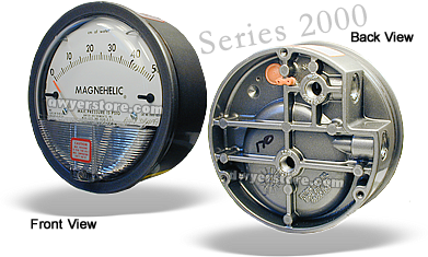
Series 2000 Magnehelic ®
Indicate Positive, Negative or Differential, Accurate within 2%
Select the Series 2000 Magnehelic gage for high accuracy–guaranteed within 2% of full scale–and for the wide choice of 81 models available to suit your needs precisely. Using Dwyer’s simple, frictionless Magnehelic® gage movement, it quickly indicates low air or non-corrosive gas pressures–either positive, negative (vacuum) or differential. The design resists shock, vibration and over-pressures. No manometer fluid to evaporate, freeze or cause toxic or leveling problems. It’s inexpensive, too.
The Magnehelic® gage is the industry standard to measure fan and blower pressures, filter resistance, air velocity, furnace draft, pressure drop across orifice plates, liquid levels with bubbler systems and pressures in fluid amplifier or fluidic systems. It also checks gas-air ratio controls and automatic valves, and monitors blood and respiratory pressures in medical care equipment.
Note: May be used with Hydrogen. Order a Buna-N diaphragm. Pressures must be less than 35 psi.
- Bezel provides flange for flush mounting in panel.
- Clear plastic face is highly resistant to breakage. Provides undistorted viewing of pointer and scale.
- Precision litho-printed scale is accurate and easy to read.
- Red tipped pointer of heat treated aluminum tubing is easy to see. It is rigidly mounted on the helix shaft.
- Pointer stops of molded rubber prevent pointer over-travel without damage.
- “Wishbone” assembly provides mounting for helix, helix bearings and pointer shaft.
- Jeweled bearings are shock-resistant mounted; provide virtually friction-free motion for helix. Motion damped with high viscosity silicone fluid.
- Zero adjustment screw is conveniently located in the plastic cover, and is accessible without removing the cover. O-ring seal provides pressure tightness.
- Helix is precision made from an alloy of high magnetic permeability. Mounted in jeweled bearings, it turns freely, following the magnetic field to move the pointer across the scale.
- Calibrated range spring is flat spring steel. Small amplitude of motion assures consistency and long life. It reacts to pressure on diaphragm. Live length adjustable for calibration.
- Silicone rubber diaphragm with integrally molded O-ring is supported by front and rear plates. It is locked and sealed in position with a sealing plate and retaining ring. Diaphragm motion is restricted to prevent damage due to overpressures.
- Die cast aluminum case is precision made and iridite-dipped to withstand 168 hour salt spray corrosion test. Exterior finished in baked dark gray hammerloid. One case size is used for all standard pressure options, and for both surface and flush mounting.
- OVERPRESSURE PROTECTION
Blowout plug is comprised of a rubber plug on the rear which functions as a relief valve by unseating and venting the gage interior when over pressure reaches approximately 25 psig (1.7 bar). To provide a free path for pressure relief, there are four spacer pads which maintain 0.023″ clearance when gage is surface mounted. Do not obstruct the gap created by these pads. The blowout plug is not used on models above 180″ of water pressure, medium or high pressure models, or on gages which require an elastomer other than silicone for the diaphragm. The blowout plug should not be used as a system overpressure control. High supply pressures may still cause the gage to fail due to over pressurization, resulting in property damage or serious injury. Good engineering practices should be utilized to prevent your system from exceeding the ratings or any component. - O-ring seal for cover assures pressure integrity of case.
- Samarium Cobalt magnet mounted at one end of range spring rotates helix without mechanical linkages.
[wpdevart_youtube width=”640″ height=”385″ autoplay=”0″ theme=”dark” loop_video=”0″ enable_fullscreen=”1″ show_related=”1″ show_popup=”0″ thumb_popup_width=”213″ thumb_popup_height=”128″ show_title=”1″ show_youtube_icon=”1″ show_annotations=”1″ show_progress_bar_color=”red” autohide_parameters=”1″ set_initial_volume=”false” initial_volume=”100″ disable_keyboard=”0″]wwO-nlf3geM[/wpdevart_youtube]
Available Models
| MODEL | DESCRIPTION |
|---|---|
| 2000-0 | range 0-0.50" w.c., minor divisions .01, calibrated for vertical scale position. |
| 2000-00 | range 0-0.25" w.c., minor divisions .005, calibrated for vertical scale position. |
| 2000-00N | range .05-0-.2" w.c., minor divisions .005, calibrated for vertical scale position. |
| 2001 | range 0-1.0" w.c., minor divisions .02. |
| 2002 | range 0-2.0" w.c., minor divisions .05. |
| 2003 | range 0-3.0" w.c., minor divisions .10. |
| 2004 | range 0-4.0" w.c., minor divisions .10. |
| 2005 | range 0-5.0" w.c., minor divisions .10. |
| 2006 | range 0-6.0" w.c., minor divisions .20. |
| 2008 | range 0-8.0" w.c., minor divisions .20. |
| 2010 | range 0-10" w.c., minor divisions .20. |
| 2015 | range 0-15" w.c., minor divisions .50. |
| 2020 | range 0-20" w.c., minor divisions .50. |
| 2025 | range 0-25" w.c., minor divisions .50. |
| 2030 | range 0-30" w.c., minor divisions 1.0. |
| 2040 | range 0-40" w.c., minor divisions 1.0. |
| 2050 | range 0-50" w.c., minor divisions 1.0. |
| 2060 | range 0-60" w.c., minor divisions 2.0. |
| 2080 | range 0-80" w.c., minor divisions 2.0. |
| 2100 | range 0-100" w.c., minor divisions 2.0. |
| 2150 | range 0-150" w.c., minor divisions 5.0. |
| MODEL | DESCRIPTION |
|---|---|
| 2300-0 | range 0.25-0-0.25" w.c., minor divisions .01, calibrated for vertical scale position. |
| 2301 | range 0.5-0-0.5" w.c., minor divisions .02. |
| 2302 | range 1-0-1" w.c., minor divisions .05. |
| 2304 | range 2-0-2" w.c., minor divisions .10. |
| 2310 | range 5-0-5" w.c., minor divisions .20. |
| 2320 | range 10-0-10" w.c., minor divisions .50. |
| 2330 | range 15-0-15" w.c., minor divisions 1.0. |
| MODEL | DESCRIPTION |
|---|---|
| 2201 | range 0-1 psi, minor divisions .02. |
| 2202 | range 0-2 psi, minor divisions .05. |
| 2203 | range 0-3 psi, minor divisions .10. |
| 2204 | range 0-4 psi, minor divisions .10. |
| 2205 | range 0-5 psi, minor divisions .10. |
| 2210 | range 0-10 psi, minor divisions .20, MP option standard. |
| 2215 | range 0-15 psi, minor divisions .50, MP option standard. |
| 2220 | range 0-20 psi, minor divisions .50, MP option standard. |
| 2230 | range 0-30 psi, minor divisions 1.0, HP option standard. |
| MODEL | DESCRIPTION |
|---|---|
| 2000-00AV | range 0-0.25" w.c., velocity 300-2000 FPM, calibrated for vertical scale position. |
| 2000-0AV | range 0-0.50" w.c., velocity 500-2800 FPM, calibrated for vertical scale position. |
| 2001AV | range 0-1.0" w.c., velocity 500-4000 FPM. |
| 2002AV | range 0-2.0" w.c., velocity 1000-5600 FPM. |
| 2010AV | range 0-10" w.c., velocity 2000-12500 FPM. |
| MODEL | DESCRIPTION |
|---|---|
| 2000-100MM | range 0-100 mm w.c., minor divisions 2.0. |
| 2000-10MM | range 0-10 mm w.c., minor divisions .20, calibrated for vertical scale position. |
| 2000-150MM | range 0-150 mm w.c. |
| 2000-15MM | range 0-15 mm w.c. |
| 2000-200MM | range 0-200 mm w.c. |
| 2000-250MM | range 0-250 mm w.c. |
| 2000-25MM | range 0-25 mm w.c., minor divisions .50. |
| 2000-300MM | range 0-300 mm w.c. |
| 2000-50MM | range 0-50 mm w.c., minor divisions 1.0. |
| 2000-6MM | range 0-6 mm w.c., minor divisions .20, calibrated for vertical scale position. |
| 2000-80MM | range 0-80 mm w.c., minor divisions 2.0. |
| MODEL | DESCRIPTION |
|---|---|
| 2300-20MM | range 10-0-10 mm w.c., minor divisions .50, calibrated for vertical scale position. |
| MODEL | DESCRIPTION |
|---|---|
| 2000-100CM | range 0-100 cm w.c., minor divisions 2.0. |
| 2000-150CM | range 0-150 cm w.c., minor divisions 5.0. |
| 2000-15CM | range 0-15 cm w.c., minor divisions .50. |
| 2000-200CM | range 0-200 cm w.c., minor divisions 5.0. |
| 2000-20CM | range 0-20 cm w.c., minor divisions .50. |
| 2000-250CM | range 0-250 cm w.c., minor divisions 5.0. |
| 2000-25CM | range 0-25 cm w.c., minor divisions .50. |
| 2000-300CM | range 0-300 cm w.c., minor divisions 10.0. |
| 2000-50CM | range 0-50 cm w.c., minor divisions 1.0. |
| 2000-80CM | range 0-80 cm w.c., minor divisions 2.0. |
| MODEL | DESCRIPTION |
|---|---|
| 2300-10CM | range 5-0-5 cm w.c., minor divisions .20. |
| 2300-30CM | range 15-0-15 cm w.c., minor divisions 1.0. |
| 2300-4CM | range 2-0-2 cm w.c., minor divisions .10. |
| MODEL | DESCRIPTION |
|---|---|
| 2000-100PA | range 0-100 Pa, minor divisions 2.0, calibrated for vertical scale position. |
| 2000-125PA | range 0-125 Pa, minor divisions 5.0, calibrated for vertical scale position. |
| 2000-250PA | range 0-250 Pa, minor divisions 5.0. |
| 2000-300PA | range 0-300 Pa, minor divisions 10.0. |
| 2000-500PA | range 0-500 Pa, minor divisions 10.0. |
| 2000-60PA | range 0-60 Pa, minor divisions 2.0, calibrated for vertical scale position. |
| 2000-750PA | range 0-750 Pa, minor divisions 25.0. |
| MODEL | DESCRIPTION |
|---|---|
| 2300-100PA | range 50-0-50 Pa, minor divisions 2.0, calibrated for vertical scale position. |
| 2300-120PA | range 60-0-60 Pa, minor divisions 2.0. |
| 2300-250PA | range 125-0-125 Pa, minor divisions 5.0. |
| 2300-500PA | range 250-0-250 Pa, minor divisions 10.0. |
| 2300-60PA | range 30-0-30 Pa, minor divisions 2.0, calibrated for vertical scale position. |
| MODEL | DESCRIPTION |
|---|---|
| 2000-1.5KPA | range 0-1.5 kPa, minor divisions .05. |
| 2000-10KPA | range 0-10 kPa, minor divisions .20. |
| 2000-15KPA | range 0-15 kPa, minor divisions .50. |
| 2000-1KPA | range 0-1 kPa, minor divisions .02. |
| 2000-20KPA | range 0-20 kPa, minor divisions .50. |
| 2000-25KPA | range 0-25 kPa, minor divisions .50. |
| 2000-2KPA | range 0-2 kPa, minor divisions .05. |
| 2000-30KPA | range 0-30 kPa, minor divisions 1.0. |
| 2000-3KPA | range 0-3 kPa, minor divisions .10. |
| 2000-4KPA | range 0-4 kPa, minor divisions .10. |
| 2000-5KPA | range 0-5 kPa, minor divisions .10. |
| 2000-8KPA | range 0-8 kPa, minor divisions .20. |
| MODEL | DESCRIPTION |
|---|---|
| 2300-1KPA | range 0.5-0-0.5 kPa, minor divisions .02. |
| 2300-3KPA | range 1.5-0-1.5 kPa, minor divisions .10. |
| MODEL | DESCRIPTION |
|---|---|
| 2000-0D | range 0-0.5" w.c. & 0-125 Pa. |
| 2001D | range 0-1.0" w.c. & 0-250 Pa. |
| 2002D | range 0-2.0" w.c. & 0-500 Pa. |
| 2003D | range 0-3.0" w.c. & 0-750 Pa. |
| 2004D | range 0-4.0" w.c. & 0-1.0 kPa. |
| 2006D | range 0-6.0" w.c. & 0-1.5 kPa. |
| 2008D | range 0-8.0" w.c. & 0-2.0 kPa. |
| 2010D | range 0-10" w.c. & 0-2.5 kPa. |
| 2015D | range 0-15" w.c. & 0-3.7 kPa. |
| MODEL | DESCRIPTION |
|---|---|
| 2000-0-SP | range 0-0.50" w.c., with set point indicator. |
| 2001-SP | range 0-1" w.c., with set point indicator. |
| 2002-SP | range 0-2" w.c., with set point indicator. |
| 2005-SP | range 0-5" w.c., with set point indicator. |
| 2010-SP | range 0-10" w.c., with set point indicator. |
Available Options
- ASF Adjustable Signal Flag
- HP High Pressure Option
- LT Low Temperatures to -20°F
- MP Med. Pressure Option
- SP Setpoint Indicator
- Scale Overlays Red, Green, Yellow, Mirrored or Combination, Specify Locations
- Mounting
A single case size is used for most models of Magnehelic® gages. They can be flush or surface mounted with provided standard hardware supplied. Although calibrated for vertical position, many ranges above 1″ may be used at any angle by simply re-zeroing. However for maximum accuracy, they must be calibrated in the same position in which they are used. These characteristics make Magnehelic® gages ideal for both stationary and portable applications. A 4-9/16″ hole is required for flush panel mounting. Complete mounting and connection fittings, plus instructions, are furnished with each instrument.